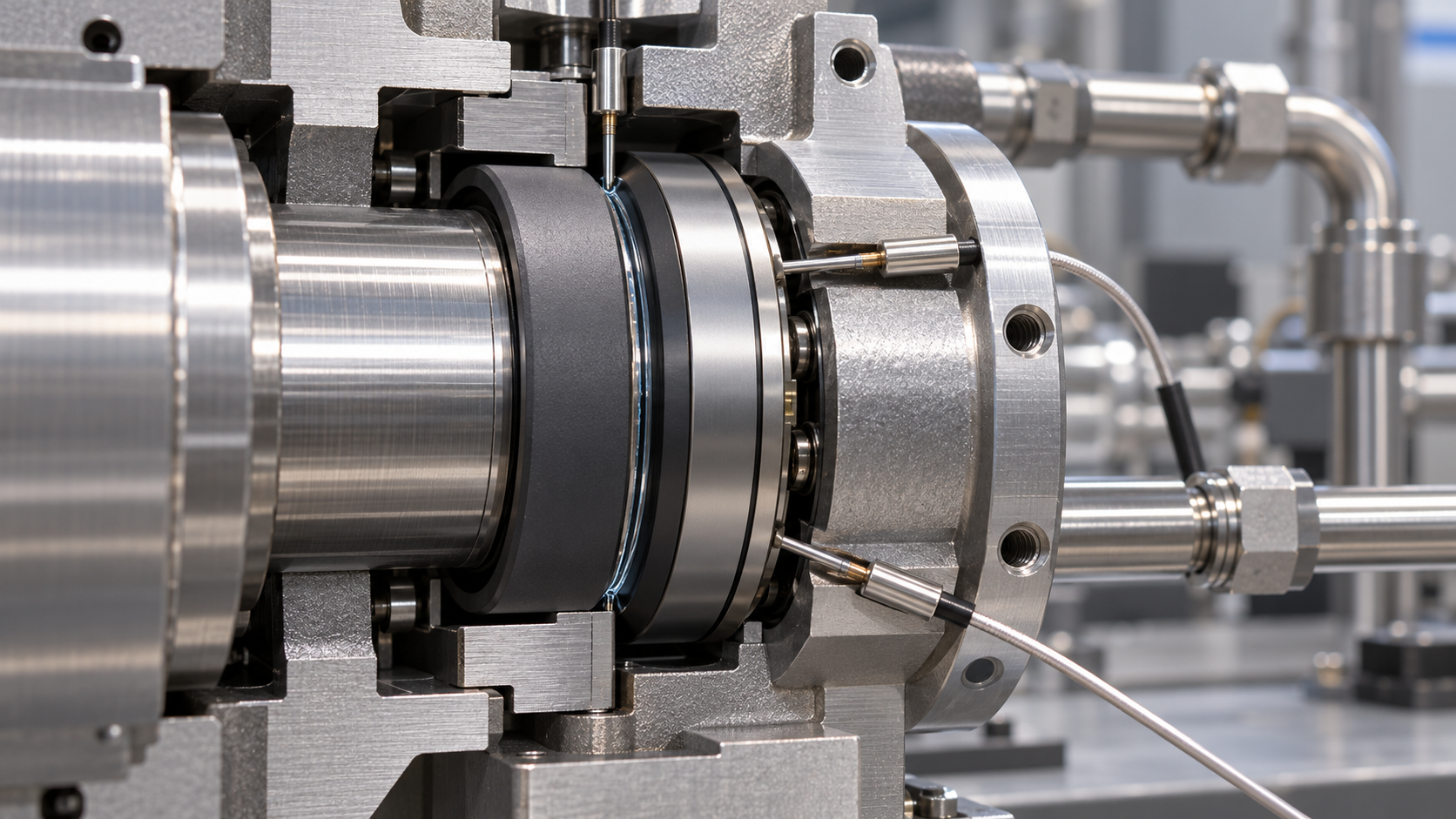
How seal face temperature profiles influence thermal distortion
Two mechanical seals operating at the same average temperature can develop very different leakage and wear patterns because their temperature distributions create different face distortions.
For technical evaluators, the decisive question is whether thermal deformation preserves a stable operating gap across the required pressure, speed, fluid, and transient conditions.
Seal face temperature profiles reveal radial, circumferential, and through-thickness gradients that average measurements conceal. These gradients interact with material properties, mounting constraints, and hydraulic loading.
A credible assessment therefore connects temperature distribution to loaded face shape, fluid-film behavior, and operating evidence. Maximum temperature alone cannot establish whether a design remains reliable.
Which temperature gradients actually change the sealing gap?
A temperature profile describes how temperature varies across the sealing face and within the ring. Each direction of variation produces different deformation risks.
Radial gradients occur between the inner and outer diameters. They can contribute to face coning, changing the radial gap distribution and concentrating load near one edge.
Through-thickness gradients develop between the rubbing surface and the ring’s rear region. Unequal expansion through this section creates bending that can substantially alter face alignment.
Circumferential gradients produce angular differences around the ring. Instead of uniform coning, the resulting deformation may include waviness, localized tilt, or discrete high-contact regions.
These patterns frequently coexist. An apparently axisymmetric radial temperature trend can conceal a local hot sector caused by restricted circulation, uneven contact, or asymmetric hardware.
The sealing gap depends on the relative deformation of both mating faces. Similar movement can partly cancel, while opposing movement can amplify gap changes.
Consequently, the hottest ring does not automatically control performance. A cooler mating ring may deform enough to change the location and severity of contact.
Evaluators should request temperature fields for both rings and compare their combined operating geometry, including pressure deformation and assembly effects, against the intended sealing mechanism.
Why average temperature cannot predict coning or leakage
Thermal strain depends on temperature change and thermal expansion coefficient. Distortion develops when that strain varies spatially or encounters restraint from surrounding components.
Uniform heating of an unconstrained, homogeneous ring mainly changes its dimensions. Nonuniform heating creates differential expansion, making bending and shape changes much more likely.
The same average temperature can therefore represent nearly uniform heating or a sharply heated face above a cooler ring body. Their distortion can differ substantially.
Material conductivity influences how readily heat spreads. Expansion coefficient influences thermal strain, while stiffness and geometry determine how thermal strain translates into deformation under constraint.
No universal rule reliably states that a hotter outer diameter always opens or closes a particular face edge. Geometry, restraint, and mating-face response determine direction.
Ring thickness, support position, drive features, interference fits, and secondary seals can all change that response. Simplified coning rules require validation for the actual assembly.
Small angular changes matter because mechanical seals operate with very small separations. Deformation that appears negligible structurally may be significant compared with the intended film thickness.
Evaluate distortion relative to the operating gap and contact distribution. Comparing it only with ring diameter, manufacturing dimensions, or bulk thermal expansion misses the functional risk.
Where damaging temperature profiles come from
Heat originates primarily from sliding contact and fluid shear, with their relative contributions changing across contacting, mixed-lubrication, and noncontacting operating regimes during seal operation.
For contacting regions, local frictional heat generation scales approximately with friction coefficient, contact pressure, and sliding speed. Uneven loading therefore creates uneven heat input.
Sliding speed increases with radius at a fixed rotational speed. However, the outer diameter is not necessarily hottest because local cooling and lubrication also vary.
Heat leaves through the rings, surrounding fluid, shaft, sleeve, gland, and associated hardware. The balance between these paths determines the resulting gradients during operation.
A flush can reduce bulk temperature yet leave a poorly cooled face sector. Flow rate alone does not establish that coolant reaches the critical region.
Deposits, obstructed passages, changing fluid properties, and gas entrainment can alter heat transfer. A previously acceptable design may develop steeper gradients without a speed increase.
Startup deserves particular attention because heat generation and heat removal develop at different rates. A safe steady-state profile can coexist with damaging transient distortion.
Shutdown, standby heating, pressure changes, and temporary loss of circulation also deserve review. The most severe thermal shape may occur outside normal continuous operation.
How distortion becomes leakage, wear, or instability
Thermal distortion matters because it changes where the faces carry load and how fluid moves through the interface. Temperature is part of a coupled process.
If deformation concentrates contact near one edge, the effective load-bearing area decreases. Local contact pressure and heat generation can rise even when total closing force remains unchanged.
This concentration may create a reinforcing cycle: localized contact generates heat, differential expansion changes face shape, and the altered shape further concentrates contact loading.
Other configurations provide stabilizing feedback by opening the heated region or redistributing load. Whether feedback stabilizes operation depends on the complete thermal and mechanical response.
If distortion increases effective separation, leakage may rise. Its magnitude also depends on pressure difference, fluid viscosity, gap geometry, and whether the fluid changes phase.
For liquid service near saturation, local heating and pressure reduction can promote vapor formation. This changes film support and heat transfer, potentially destabilizing operation.
Gas seals require different film models because compressibility and engineered lift features govern behavior. Liquid-film assumptions should not be transferred directly to those designs.
Wear tracks and leakage trends provide useful clues, but neither uniquely identifies thermal distortion. Misalignment, contamination, pressure deformation, and assembly errors can produce overlapping symptoms.
Which material and geometry choices improve thermal behavior?
Material selection should address the full combination of conductivity, expansion, stiffness, friction, chemical compatibility, and wear behavior. A single favorable property cannot establish suitability.
Higher conductivity often reduces temperature differences by spreading heat more effectively. Its benefit still depends on whether the surrounding assembly provides an effective heat-removal path.
A lower expansion coefficient reduces thermal strain for a given temperature change. However, the assembled response also depends on restraint and the mating ring’s properties.
Material grades matter. Different silicon carbide, tungsten carbide, or carbon grades can have different thermal and mechanical properties, so generic material labels are insufficient.
Ring geometry controls both heat flow and bending response. Increasing thickness may improve bending stiffness while changing thermal resistance, heat capacity, and transient response.
Face width also involves tradeoffs. Changing it affects contact loading, heat generation, conduction distances, and fluid-film behavior; wider faces do not automatically provide greater reliability.
Support geometry deserves equal attention. A ring seated against a shoulder can distort differently from an otherwise identical ring supported at another radius or location.
Design improvements should demonstrate reduced harmful gap variation across operating cases. A lower peak temperature is valuable, but it does not independently prove better sealing performance.
What should a credible thermal analysis include?
Begin with the service envelope: pressure, speed, fluid composition, inlet temperature, expected contamination, cooling conditions, and relevant transients. Define acceptance criteria before interpreting results.
The thermal model should represent heat generation, heat partition between the faces, conduction through components, and heat transfer to surrounding fluids with defensible boundary conditions.
Heat partition should reflect the interface physics and thermal properties. Assuming an arbitrary equal split can misrepresent each ring’s temperature field and subsequent deformation.
Structural analysis should include pressure loads, spring or bellows forces, mounting constraints, and relevant contacts. Thermal deformation must be assessed alongside these other shape changes.
An axisymmetric model can efficiently evaluate uniform geometry and loading. Circumferentially uneven cooling, drive features, or localized contact may require a three-dimensional treatment instead.
Where the gap strongly affects heat generation and film pressure, a prescribed heat load may be inadequate. Coupled thermoelastic or thermoelastohydrodynamic analysis may be necessary.
Request sensitivity studies for uncertain friction, convection, material properties, and contact conditions. A design that works only under one favorable assumption has limited demonstrated margin.
Mesh and time-step checks should support the predicted gradients and deformation. Numerical convergence establishes solution consistency, while experimental comparison addresses whether the model represents reality.
How can measurements confirm the predicted temperature profile?
Validation should combine thermal measurements with functional evidence, including leakage, torque where measurable, operating stability, and post-test face condition. Agreement in temperature alone is insufficient.
Embedded thermocouples measure temperature near their installation points, rather than directly at every location on the interface. Sensor depth affects amplitude and response time.
Infrared measurements require suitable optical access and emissivity treatment. Measurements of exposed surfaces should not automatically be interpreted as temperatures within the concealed sealing interface.
Compare measurements with predictions at matching locations and times. Comparing a calculated interface maximum with a thermocouple behind the face can create misleading disagreement.
Use multiple radial and circumferential measurement positions where practical. A single sensor may track overall heating while missing the gradient responsible for damaging deformation.
Transient tests should reproduce relevant startup rates, pressure sequences, and cooling interruptions. Test duration should capture both early peaks and the approach to thermal equilibrium.
Post-test wear patterns can support a predicted contact location, especially when combined with leakage and thermal histories. They should remain corroborating evidence rather than standalone proof.
A persuasive validation report explains measurement uncertainty and unresolved differences. It also identifies which operating conditions were demonstrated and which remain dependent on model extrapolation.
What evidence should technical evaluators require before approval?
Ask suppliers to connect operating conditions, temperature distributions, relative face deformation, and observed performance. Separate plots become useful when their causal relationship is explained.
Require results for both mating rings, including radial profiles, relevant circumferential variation, and through-thickness temperature differences. Review transient extremes alongside steady-state conditions for both rings.
Request the predicted loaded face shape and minimum film thickness where applicable. For contacting seals, examine contact location, pressure distribution, and expected wear implications.
Acceptance limits should match service requirements, fluid behavior, and the seal design. There is no universal temperature gradient or coning limit suitable for every application.
Standards compliance provides a qualification framework, but it does not replace application-specific evidence. Confirm that documented testing and analysis cover the proposed operating envelope.
Prefer design changes that improve performance across plausible variations in cooling, friction, and operating conditions. Narrow nominal improvements may disappear when realistic uncertainties are included.
The practical judgment is straightforward: seal face temperature profiles matter when they change the interface enough to affect containment, lubrication, wear, or operational stability.
Approve a design when analysis and testing demonstrate acceptable combined face behavior across required conditions, with quantified uncertainty and clear limits on the evidence supporting that decision.